
The research aims to design an access control and attack detection mechanism based on an optimized deep learning approach. The schematic depiction of the proposed workflow is illustrated in Fig. 2. First, through the verifier, the IoT devices gather patient data and register it with the edge server. Following registration, the Blockchain-enabled security architecture stops unwanted access and confirms the data’s legitimacy. The Proof of Authority (PoA) consensus mechanism and the IPFS, which are components of the blockchain-enabled security architecture, protect data from security breaches and enforce security regulations. Additionally, the optimized Radial basis neural network is used to extract the most important features, including entropy, average flow, growth of flow and port, and land, to detect the attack. The proposed radial basis network checks the transactions as malicious and normal. Moreover, the hybrid optimization algorithm fine-tunes the network parameters thus enabling accurate attack detection.
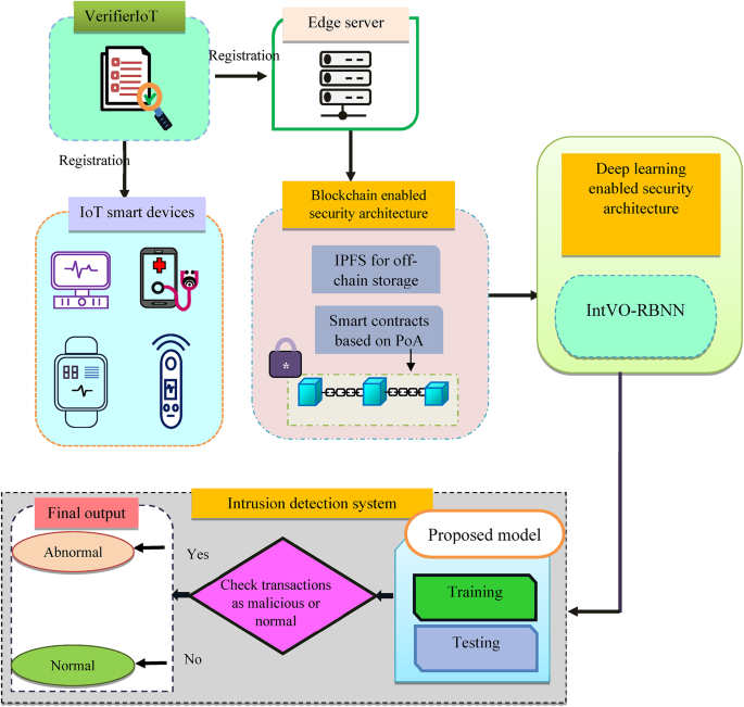
Schematic representation of the proposed model.
Access control scheme in blockchain systems
An access control mechanism in the blockchain system is designed to prevent unauthorized access to the medical information of patients, which enhances data security and integrity.
Initially, the health ministry or the hospital establishes the corresponding departments, and the PA2C protocol is intended to verify access to the legitimate user. The health ministry then assigns a specific person to each department. If the patient and the doctor \(d_{l}^{u}\) communicate, the data is saved and accessible through the doctor whenever necessary. Table 1 and 2 lists the steps involved in the internal access control method.
Setup and establishment of EHR systems
In this phase, initially, the healthcare ministry classifies data regarding several departments. For each department, a legitimate doctor is allocated as a legalized user. Moreover, Information exchanged between the patient \({P_j}\) and an authorized physician is recorded in the ledger. Only the designated physician from the relevant department has access to the material.
User request and data retrieval in the EHR system
Initially, to access the data the doctor \(d_{l}^{u}\) sends the identity \(\left( {I{d_{d_{l}^{u}}}} \right)\), and the system verifies the authenticity of the doctor. Once the verification is successful, the authorized user is permitted to login into the portal. Following the process of verification, the user requests the data, and the system promptly responds with a user inquiry and acknowledges it. After questions are answered, policies are created for both the owner and the user to prevent future legal requirements. Additionally, the users’ level of sensitivity is evaluated at the same time. Users are only granted access to the data if their degree of sensitivity is surpassed. The user receives the data after it has been validated. Figure 3 depicts a schematic perspective of the EHR systems’ setup and establishment phase.
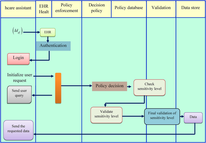
Schematic perspective of the EHR systems’ setup and data retrieval phase.
System entitles
The elements of the system include the registration phase, which detects requests, and the blockchain, which is where the encryption and storing process occurs. The system entities ensure secure, transparent, and efficient handling of requests and data storage.
a) Registration phase.
The registration phase is the fundamental process in the blockchain system, in which the user needs to interact with the system must be registered, which provides the necessary information and credentials to create a unique identity. Once registration is completed, the system can identify requests from the users that ensure the authenticated user only accesses the data stored in the blockchain storage system. Data providers and users are ensured to be recorded on the blockchain during the registration process. Consider that if a user z wants to access their patient’s data in the EHR, the patient must give the EHR their user identity \(\left( {{J_z},{J_{pwd}}} \right)\) to do so. The steps involved in the registration phase are depicted in Fig. 4, which are described as follows.
Initially, the patient, who is the data provider, estimates the public key\({h_k}\) and sends it to the blockchain together with the user’s identity. The public key can be calculated as,
$${h_k}=Ha\left( {{J_z}} \right)\left\| {En\left( {{J_{pwd}}} \right)} \right. \oplus \bmod e$$
(6)
Where \(En\left( {} \right)\) signifies the encryption function, \(Ha\left( {} \right)\) denotes the hash function, and e indicates the prime order. The user identity typically consists of user ID and password, which is sent to the blockchain for verification, once verified, the blockchain securely stores user’s identity\(\left( {J_{z}^{*},J_{{pwd}}^{*}} \right)\). The security factor is then generated by the blockchain storage system in order to determine the private key of the security factor, and the private key of the user can be estimated as follows,
$${h_k}=Ha\left( {J_{z}^{*}} \right)\left\| {En\left( {J_{{pwd}}^{*}} \right)} \right. \oplus \bmod e$$
(7)
The user’s private key is constructed as follows. The data user now receives the private key that the blockchain created. If \({h_k}^{*}={h_k}\), the data owner has been properly verified and registered with Trusted Certificate Authority (TCA).
Schematic illustration of user registration and owner registration phase..
Owner registration phase
During this phase, the owner (patient) must submit it identify\(\left( {P_{{Id}}^{j},P_{{pwd}}^{j}} \right)\) to the blockchain. The following steps are involved in this process.
First, the user identification is sent to the blockchain by the data owner, who also evaluates the public key \({h_j}\).
$${h_j}=Ha\left( {P_{{id}}^{j}} \right)\left\| {En\left( {P_{{pwd}}^{j}} \right)} \right. \oplus \bmod e$$
(8)
User ID and password are sent to the blockchain for verification, and the user’s identity is stored as \(\left( {P_{{Id}}^{{j*}},P_{{pwd}}^{{j*}}} \right)\) Following that, the blockchain storage system generates the security factor and the private key can be approximated using the following formula,
$${h_j}=Ha\left( {P_{{id}}^{{j*}}} \right)\left\| {En\left( {P_{{pwd}}^{{j*}}} \right)} \right. \oplus \bmod e$$
(9)
At this point, the data user receives the private key that the blockchain generated. If the private key matches the expected criteria \({h_j}^{*}={h_j}\), the data owner is successfully validated. Upon successful validation, the data owner is registered in the blockchain. The registration phase guarantees that the identity of the data provider and the user is securely verified, and their private key is safely generated and transmitted, enabling secure interactions within the blockchain system. Once the registration is successful, users can begin accessing and storing data for which they have signed a smart contract.
b) Contract sign and acknowledgment.
The contract sign and acknowledgment phase serve as a robust and secure method, which involves the creation of a unique digital signature that is shown in Fig. 5. Here, to sign a contract the following procedures are done.
Initially, to create a smart contract the data owner shares its identity and password\(\left( {P_{{Id}}^{j},P_{{pwd}}^{j}} \right)\) to the blockchain, and the blockchain verifies the incoming patient is entered into the blockchain database. If j is available in blockchain, it determines a security degree, which can be calculated using the user attributes and credentials. The security degree \({\delta _1}\) can be formulated as follows,
$${s_1}=j * \left( {{\delta _1} \oplus {\gamma _1}} \right)+{h_p}$$
(10)
where \({\gamma _1}\) denotes a random number, \({h_p}\)indicates the private key. Similarly, the calculation for \({s_2}\) is expressed as follows,
$${s_2}=j * \left( {{\delta _o} \oplus {\gamma _1}} \right)+{h_p}$$
(11)
When the security key \({s_1}={s_2}\), the acknowledgment \(\left( {Ack} \right)\) is shared to the IPFS. Once acknowledged by the blockchain, the security keys F are released,
$$F=\left\{ {{F_1},{F_2},….{F_N}} \right\}$$
(12)
where \(\left\{ {{F_1},{F_2},….{F_N}} \right\}\) signifies the security keys which have a range between 1 to N, the security keys are forwarded to IPFS. Furthermore, the address location \(\left( {Loc} \right)\) and corresponding keys \({F_c}\)are generated and stored in the blockchain. In addition, the patient sends a request for data storage to the blockchain, and the smart contract communicates the data request to the IPFS. The storage system replies to the address location of requested data and shares the key \(\left( {lo{c_d},{F_{cd}}} \right)\) to the data owner. At the same time, the data is managed as chunks and encrypted as follows,
$$En\left( D \right)=En\left\{ {{d_1},{d_2},….{d_l}….{d_N}} \right\}$$
(13)
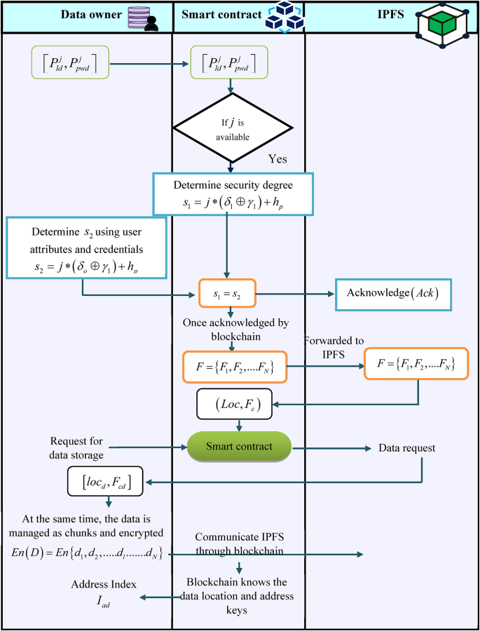
Contract sign and acknowledgement phase.
Each chunk is encrypted separately and communicated to IPFS through blockchain. The blockchain knows the data location and address keys. Moreover, the address index \({I_{ad}}\) is shared with the data owner. As a result, the contract sign and acknowledgment phase guarantees that the data owner’s identity is safely confirmed and that blockchain and IPFS are used to store and manage their data securely. The security and dependability of EHR data sharing are improved by the use of smart contracts, encryption, and secure key management.
c) Authentication for access and decryption.
Whenever the new user (doctor) wants to access the data to suggest any disease-related instruction, he needs to be acknowledged through blockchain. Authentication for data access and data decryption verifies the identity of the user, which ensures data confidentiality as well as enhances data security from unau \({\psi _{ID}}\), department \({\psi _{dept}}\), specialization \({\psi _{spe}}\), and hospital ID \({\psi _{{H_{id}}}}\), to the blockchain. Furthermore, the blockchain checks the user details in its directory. Based on the user request for the private key of the blockchain, a key \({L_2}\) is generated, which is represented as follows,
$${L_2}=\varpi *{h_p} \oplus {\delta _1}*{h_j}$$
(14)
where \(\varpi\) specifies the random security integer, \({h_p}\) denotes the private key, and \({h_j}\) indicates the public key. To verify the genuineness of the doctor, the authentic key \({L_1}\) provided during registration and the key generated from the blockchain are compared as follows,
If \({L_1}={L_2}\), the doctor is genuine, and the data request from the doctor is informed to the IPFS via blockchain. The blockchain shows the address location and shares it with the doctor \(\left( {Loc} \right)\)as well as releases the key \({F_c}\). With the help of security keys, the doctor can decrypt the data from the IPFS storage, the decryption can be represented as follows,
$$Dec\left( D \right)=Dec\left\{ {{d_1},{d_2},….{d_l}…..{d_N}} \right\}$$
(16)
Once the doctor gets permission to access the data or dashboard, they will connect the patient for any health assistance. Because a central authority is no longer necessary, the blockchain lowers the possibility of a single point of failure and increases the robustness of the system. The schematic illustration of the Authentication for access and decryption phase is shown in Fig. 6.
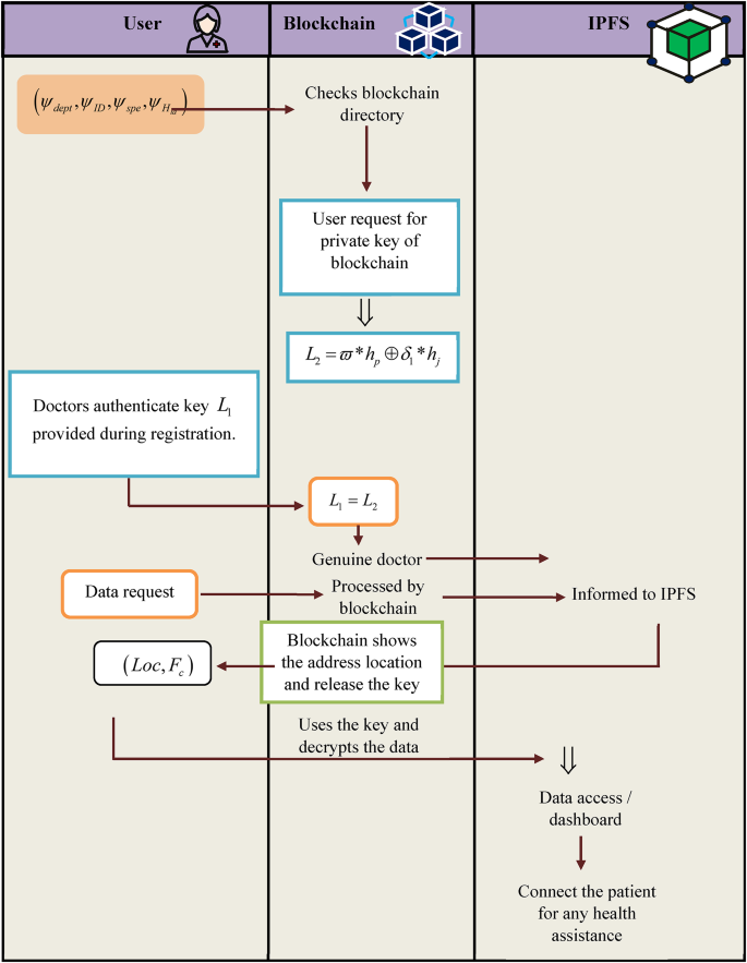
Authentication for data access and decryption.
Attack detection using radial basis neural network
The hospital portal stores the patient data that has been gathered, and it uses the radial basis network to evaluate the data for attack detection. The network transmission parameters are employed to carry out the attack detection, which facilitates the identification of unidentified network users. Without compromising data quality, the detection would guarantee the safe transfer of medical data over the system.
Feature extraction
For effective attack detection performance, the significant features including the growth of flow, average flow, entropy, port, and Land are extracted, which is explained as follows,
a) Entropy: The entropy features are significant for measuring the randomness of specific attributes in the header of the network packets. The estimated entropy values offer information associated with the detection or identification of attacks25. By examining the series of continuous packets, packet creation rate, source port number, and destination IP address the entropy is measured is mathematically described as follows,
$$Q= – \sum\limits_{{k=1}}^{n} {{I_k}} \log {I_k}$$
(17)
Where Q specifies the entropy, n indicates the total number of packets, \({I_k}\) denotes the probability of each separate source IP address. The entropy of source port numbers is calculated based on the predefined threshold, a significant drop in the entropy of source port numbers can indicate a potential DDoS attack. On the other hand, the packet creation rate’s entropy is defined as the frequency at which packets are generated and sent over the network. In normal conditions, the packet creation rate is normal, while during the DDoS attack, the packet creation rate spikes dramatically. The entropy of the destination IP address is utilized to determine whether the traffic is being directed towards a single target or multiple targets. The value drops with the maximum data flow, indicating the risk of an attack.
b) Average Flow: Since it can be difficult to identify the attacker’s initial source, the average packet flow is assessed to identify the DDoS attack using the median computation, which is represented as,
$$Median\left( g \right)=\left\{ \begin{gathered} g\left( {\frac{{g+1}}{2}} \right)\,\,\,\,\,\,\,\,\,\,\,\,\,\,\,\,\,\,\,\,\,if\,\,n\,\,is\,\,odd \hfill \\ \frac{{g\left( {\frac{g}{2}} \right)+g\left( {\frac{{g+1}}{2}} \right)}}{2}\,\,\,\,if\,\,n\,\,is\,\,even \hfill \\ \end{gathered} \right.$$
(18)
Where g indicates the packet per flow. The average byte/flow is used to calculate the payload size, an increase in value indicates the risk of an attack. A smaller number indicates the fewest false positives. The average duration/flow property assesses the flow time that occurs in the flow table. The flow features \(Av{g_F}\)improve the attack detection accuracy and can detect anomalies in network traffic patterns that are indicative of DDoS attacks, allowing for timely and accurate detection and mitigation.
c) Growth of flow and port: The growth parameter tracks the increase in data flow over time, for effective attack detection the single flow growth feature is extracted, in which for DDoS attacks the data growth is very high. The single flow growth \(\left( {sfg} \right)\) calculation can be performed as follows,
$$sfg=\frac{{{F_{num}} – 2 \times P{F_{num}}}}{{{T_{\operatorname{int} }}}}$$
(19)
where \(P{F_{mun}}\) denotes the number of flow pairs, and \({T_{\operatorname{int} }}\) specifies the time interval, and a total number of flows is denoted as \({F_{mun}}\). The network ports are responsible for sending and receiving the data, unusual activity on a port can indicate an attempt to exploit a vulnerability. The variation in port growth \(Dif{f_{PG}}\) can be calculated as follows,
$$Dif{f_{PG}}=\frac{{P{t_{num}}}}{{{T_{\operatorname{int} }}}}$$
(20)
where \(P{t_{mun}}\) represents the port number. In addition, the pair flow has the identical source port and destination IP, and the fair flow’s elevation expresses the risk of a DDoS attack, which is calculated as
$$P{F_{per}}=\frac{{2 \times P{F_{mun}}}}{{{F_{num}}}}$$
(21)
where \(P{F_{per}}\) signifies the fair flow percentage
d) Land: Land\(\left( {LD} \right)\) is a type of Local Area Network Denial attack in which the attackers repeatedly send TCP packets to the nodes, causing the target system or portal to crash. Therefore, taking land into account as one of the aspects would allow for the tracking of clear messages to the IoT nodes. Collectively, these attributes contribute to the deep learning model to detect patterns that indicate an attack, and the obtained parameters are integrated to form a feature vector, and provided into the proposed IntVO-RBNN model which can be described as,
$${f_{vec}}=\left\{ {Q,Av{g_F},sfg,Dif{f_{PG}},LD} \right\}$$
(22)
Radial basis neural network architecture for attack detection
The research intended to design an IntVO-RBNN model for effective attack detection, which is made up of several simple processing units, or neurons, that are connected. The IntVo-RBNN model gains problem-solving skills by suitably modifying the linkages’ strength based on incoming data. Additionally, it is easily adaptable to different settings through learning. In addition, it can handle probabilistic, ambiguous, noisy, and inconsistent data26. The traditional attack detection models have faced several challenges regarding model complexity, anonymization services, and IP spoofing. To tackle these challenges, this research integrates the benefits of the IntVO algorithm into the RBNN model that effectively tunes the model’s hyperparameters.
The radial basis function (RBF) concept is one of the most widely used and very effective, which learns the nonlinear mapping between an input space27. In this research, the \(\eta\)-dimensional input \({f_{vec}}\) is sent straight to a hidden layer in an RBF. Assume that the hidden layer has \(\kappa\)neurons. The Euclidean distance between the input and a \(\eta\)-a-dimensional prototype vector determines the activation function applied by each of the neurons in the\(\kappa\) hidden layer. If the distance between the center\({\nu _1}\)of each RBF \({\Psi _k}\)and the input vector is equal to zero then the contribution of this point is 1, however as the distance rises, the contribution goes to 0. The distance can be mathematically formulated as follows,
$$Dis=\left\| {{f_{vec}} – {\nu _1}} \right\|$$
(23)
There may be multiple predictor variables in the input layer, each of which is connected to a separate neuron, and propagates input to the hidden layers. Numerous RBF units \({\Psi _{\tau b}}\) with Gaussian kernels and bias \(\beta\) are part of the hidden layer. A center \({\nu _k}\) and a width \({\omega _1}\)determine the k-th Gaussian function. The IntVo-RBNN classifier does the nonlinear transformation in the hidden layer \({b_k}\)as follows,
$${b_k}\left( {{f_{vec}}} \right)=\exp \left( { – {{\left\| {{f_{vec}} – {\nu _k}} \right\|}^2}/w_{k}^{2}} \right)$$
(24)
Every hidden neuron has a parameter called a prototype vector. Each hidden neuron’s output is then sent to the output layer after being weighted. The weighted hidden layer neurons’ sums make up the network’s outputs, which is mathematically denoted as follows,
$${q_x}\left( {{f_{vec}}} \right)=\sum\limits_{{k=1}}^{{\tau b}} {{W_{xk}}.} {b_k}\left( {{f_{vec}}} \right)+\beta$$
(25)
Where \({W_{xk}}\) denotes the layer weights, the form of the RBF functions at the hidden units, the number and location of the centers, and the method for determining the network weights all have a significant impact on the IntVo-RBNN model’s performance. The output layer of the proposed model effectively detects the presence of attack with better accuracy. The IntVo-RBNN model is a three-layer network, which is depicted in Fig. 7. The layer weights and biases are optimally tuned using the IntVo algorithm.
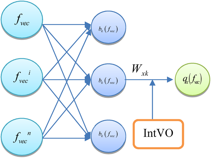
Architecture of the IntVO-RBNN model.
Intelligent voyage optimization algorithm
Motivation
The IntVO algorithm is designed to optimize the hyperparameters of the RBNN model, which simulates the traveling and intelligent hunting behaviors of osprey19 and coot28. Similar to other metaheuristic algorithms, the fundamental coot algorithm has a low diversity tendency, a poor convergence speed, and an inadequate balance between exploitation and exploration. The local optimal solution may trap the approach. To expand the fundamental COOT method’s local and global search trends, this research integrates the intelligent hunting behaviors of osprey.
Inspiration
The collective activities of coots and osprey serve as the foundation for the IntVO algorithm. The coots’ collective activities include both regular and erratic motions across the water’s surface. Each individual in the group makes an effort to get closer to the goal of attaining the best target. As a result, they revise their current stances in light of the group leader’s positions. For instance, the random movement to one side and the other, chain movement, positional adjustment based on the group leaders, and leader movement play a significant role in the proposed algorithm29. In addition, the key source of inspiration for IntVO is the method used by ospreys to locate, capture, and move their prey to a convenient location for consumption when hunting fish from the ocean. Mathematical models are used to simulate the IntVO implementation processes in two phases. The clever natural actions of ospreys, such as catching fish and transporting them to a suitable location for consumption, can serve as the basis for the development of new optimization algorithms. As a result, the IntVO algorithm is designed using mathematical modeling of these intelligent osprey behaviors.
Solution initialization
In the IntVO algorithm, the solutions are randomly generated based on layer parameters such as weights and biases. Here, the initialized solution for parameter tuning is mathematically indicated as follows,
$$M=\left\{ {{M_1},{M_2}…{M_y},…{M_N}} \right\}$$
(26)
where M indicates the solutions and \(M \in \left\{ {{W_{xk}},\beta } \right\}\)
Fitness evaluation
The evaluation of fitness function is the process of assessing the quality of potential solutions to an issue using a fitness function. In the proposed IntVO algorithm, the fitness function aids the algorithm in deciding which solutions to retain and which to discard. The mathematical formulation can be estimated as follows,
$$Fit\left( {M_{y}^{{t+1}}} \right)=Max\left( {accuracy\left( {M_{y}^{{t+1}}} \right)} \right)$$
(27)
Solution update
Once all the solutions are evaluated for their strength, the first two best solutions are declared, which remain as the leader for the search and hunt processes associated with the proposed algorithm. Based on the conditional factor, the algorithm enables two phases such as exploitation and exploration, which are detailed in the subsequent section.
Stage 1: Exploitation \(\left( {\Upsilon \leqslant 1} \right)\): When the conditional factor \(\Upsilon\) is less than or equal to one, the solution searches for the best position inside the search boundary. In this phase, the solution updation can be performed based on the leading solution. In addition, the use of guiding factor is used to update the position of the solutions through the leaders’ average location
$$M_{y}^{{t+1}}=M_{y}^{t}+{r_1}+\left( {M_{G}^{1} – M_{i}^{t}} \right)+{r_2}*\left( {M_{G}^{2} – M_{i}^{t}} \right)+{r_3}\left( {{M_{avg,G}} – M_{i}^{t}} \right)$$
(28)
where \(M_{G}^{1},M_{G}^{2}\) specifies the first two best solutions, \(M_{{avg,G}}^{{}}\) denotes the global average of solutions for the previous 3 iterations, \({r_3}\) denotes the random number\(\in \left( {0,1} \right)\), \({r_1}\) indicates the guiding factor, which can be estimated as follows,
$${r_1}=\left( {\frac{{Fit\left( {M_{G}^{1}} \right) – \left( {\frac{{Fit\left( {M_{G}^{{t – 1}}} \right)+Fit\left( {M_{G}^{{t – 2}}} \right)}}{2}} \right)}}{{Fi{t_{\hbox{max} }}\left( {M_{G}^{t}} \right)}}} \right)$$
(29)
where \(Fi{t_{\hbox{max} }}\left( {M_{G}^{t}} \right)\) signifies the fitness acquired for best solutions till the current iteration, \(M_{G}^{{t – 1}},M_{G}^{{t – 2}}\)represents the best solutions in the previous iteration, \({r_2}\) denotes the progressive factor that drives the solutions to global points, and can be estimated based on the velocity corresponding to the first two best solutions.
$${r_2}=\frac{{V\left( {M_{G}^{1}} \right) – V\left( {M_{G}^{2}} \right)}}{{{V_{Max}}}}$$
(30)
The above equation \({V_{Max}}\) denotes the maximum velocity.
Stage 2: Exploration\(\left( {\Upsilon >1} \right)\) :The exploration phase represents that the condition factor is greater than one, therefore the solution searches out of the search boundary to obtain optimal results. Based on the attacking behaviors of osprey, the position of the solution in the search space altered dramatically, enhancing the algorithms’ ability to explore and find the perfect location while avoiding local optimality. Here, the mathematical formulation for solution updation can be performed using the velocity of the random solution and the random position of the solution respectively.
$$M_{y}^{{t+1}}={M_{rand}}+{r_4}+\left( {{M_{rand}} – M_{y}^{t}} \right)+{V_{rand}}$$
(31)
where \({M_{rand}}\) signifies the random position of the solution, \({V_{rand}}\)denotes the velocity of the random solution, and \({r_4}\)indicates the random number \(\in \left( {0,1} \right)\).
Termination
When the algorithm stops its iteration and declares the global best solution for effective parameter tuning. The flow diagram of the proposed IntVO algorithm is depicted in Fig. 8.
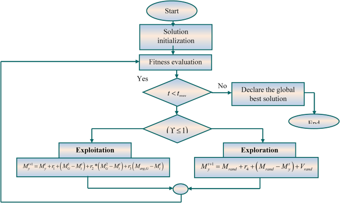
Flowchart of the proposed IntVO algorithm.